DESIGN PRINCIPLES
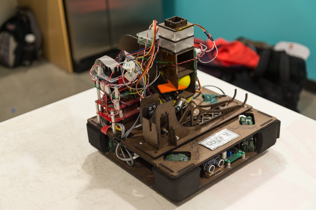
Our robot is designed to be effective, fast and reliable. Our overall strategy for the game is to avoid line following, to minimize our robot's rotation and to shoot from a preset constant distance. This decision led us to create a robot using Omni-Directional wheels and a reversible shooting platform. By not following the line, we created a more versatile and faster robot that can move anywhere in the field, and is not restricted to one area. By preventing the robot to rotate and only using coordinate navigation, we avoided the problems that most teams ran into when they tried to locate frequency beacons at the shooting areas. By only allowing it to shoot from one distance, we only had to calibrate the shooter once and be sure that it will shoot reliably to all target areas. Following these strategies, we reduced the game to two simple steps: just travel to a location without rotating, perform a task then repeat. This process proves to be simple yet most effective in this competition.
DRIVETRAIN
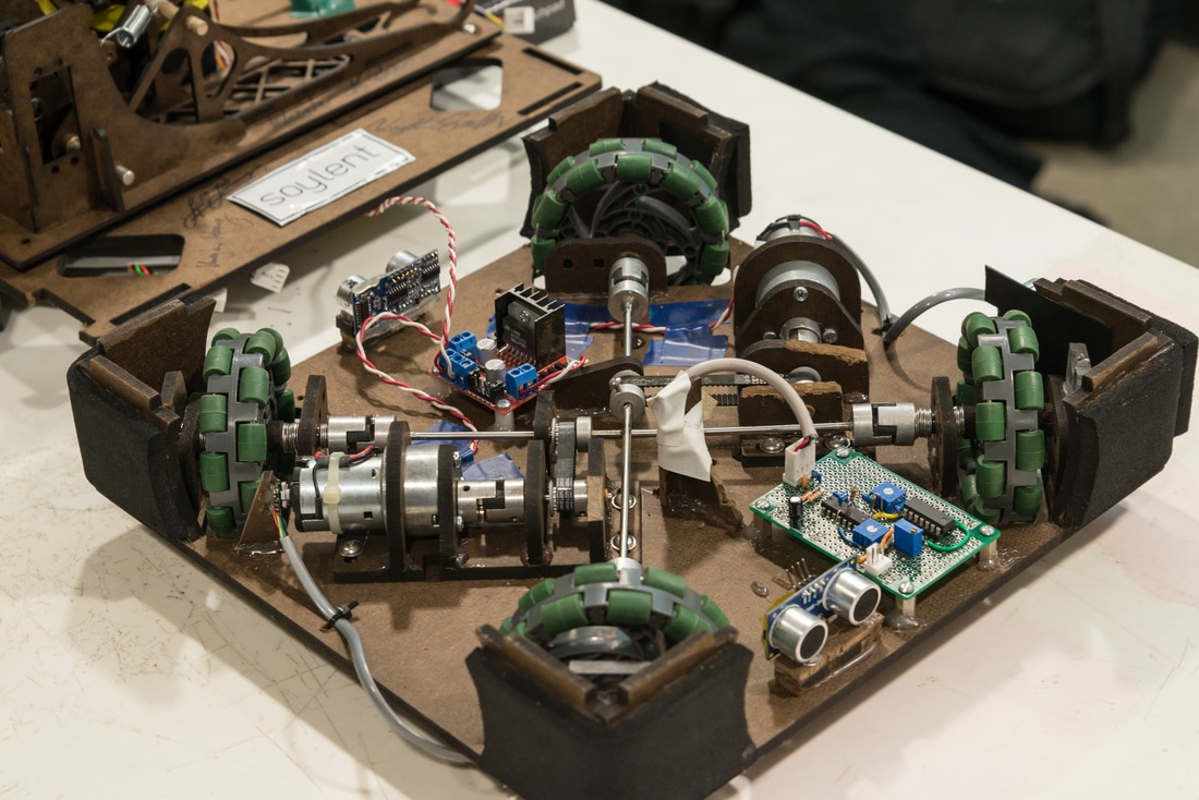
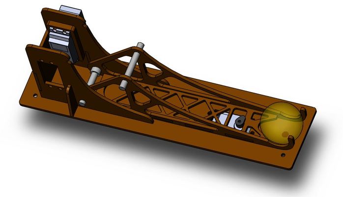
The most iconic part of our robot is the drivetrain. In order to move in grid pattern without rotation, we decided to use four Omni-Directional wheels. Although having four motors will make the use of these wheels mechanically easier, we were only allowed to use two. This restriction led us to the crossing shafts configuration and timing belt drives where one motor drives two wheels. Each motor is connected to a spider coupling which move the timing belt. The timing belt moves the center shaft and the two wheels connecting to it. The motors are also on bases that can be slid back and forth to tighten the timing belts. Each wheel is connected to the shaft by a spider coupling and is locked in place with an acrylic plate so it can not come off. All radial stresses on the shafts are taken up by self-lubricating brass bushings. With this system, we achieved maneuvering capability no one else has - that is, the ability to move to any location without rotating our robot which makes shooting the target very easy and effective as the robot only faces one direction. You can see the drivetrain in action here.
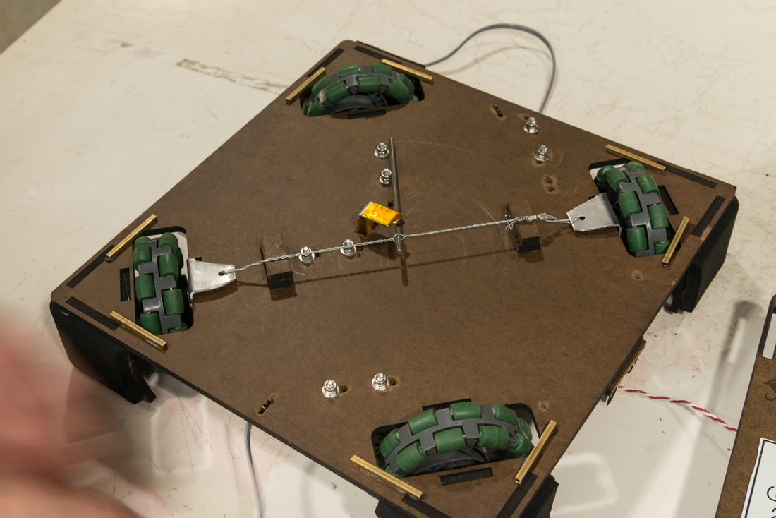
By using the crossing shaft configuration described above, we faced a problem where the wheels on the top shaft are pushed up causing them to contact the ground with less force so they occasionally slipped. We fixed this problem by inserting a cable on the bottom plate between these two wheels and tightening it so the two sides are pushed down and all four wheels are on the same level. This cable enables our robot to move perfectly straight without slipping.
BALL DISPENSER AND SHOOTER
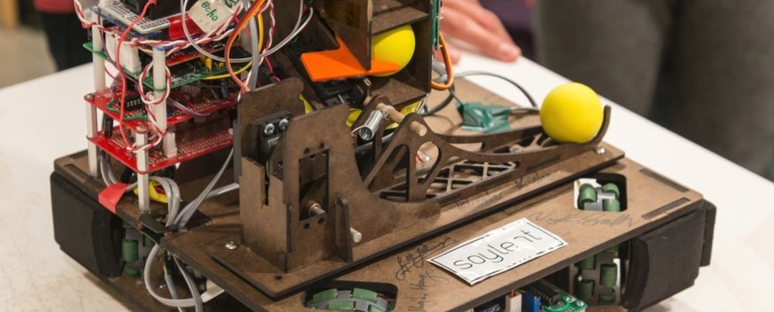
Our ball dispense is a gravity-fed chute that holds four balls. We constructed the shooting mechanism using three servos: one for dispensing the ball to the shooter, one for latching the shooter in place or unlatching to shoot, and one for extending the shooter spring. We chose to make a catapult because we knew it is more precise than most fly-wheel shooters. The shooting process is very simple and we can tune our spring servo angle to shoot from any distance we want. The catapult has a ramp structure so we can dispense the ball in the middle and the ramp will guide the ball down to the holder at the end. The shooting platform is also reversible which allows us to switch the shooting direction depending on the current side of the field we are on.
The shooting process can be listed step by step as follow:
The shooting process can be listed step by step as follow:
- The shooter is reset when the spring servo relaxes the spring
- The dispense servo moves its arm out to dispense the ball to the catapult's ramp
- The dispense servo moves its arm back and locks another ball in place
- The latch servo latches the shooter arm in place
- The spring servo moves its arm up to tension the spring
- The latch servo unlatches, releasing the catapult and the ball flies off
LED TOWER
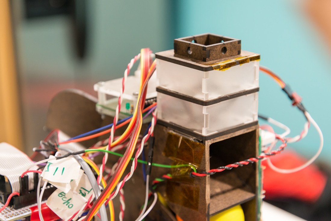
One of the requirements for this project is to have our robot clearly indicating when the game is in progress and the current team of our robot (red or green). We constructed this tower on top of our ball storage using acrylic so the light from the indication LEDs shines out and can be seen from a distance in all direction. We also accommodated for IR phototransistors at the top of the LED tower (see the four holes at the very top in the picture), however they were left empty at the end since we decided not to use IR sensing and use ultrasonic sensor instead.
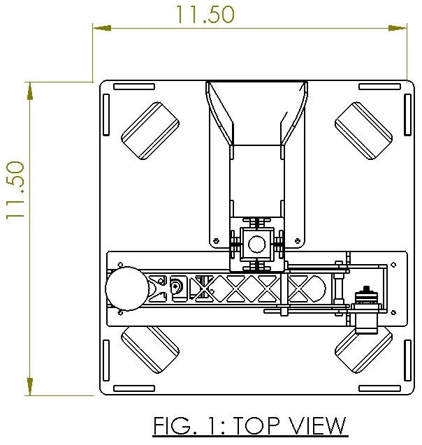
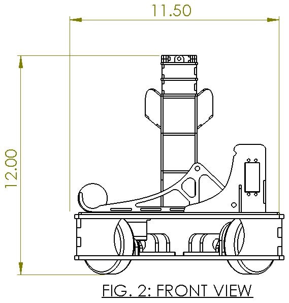
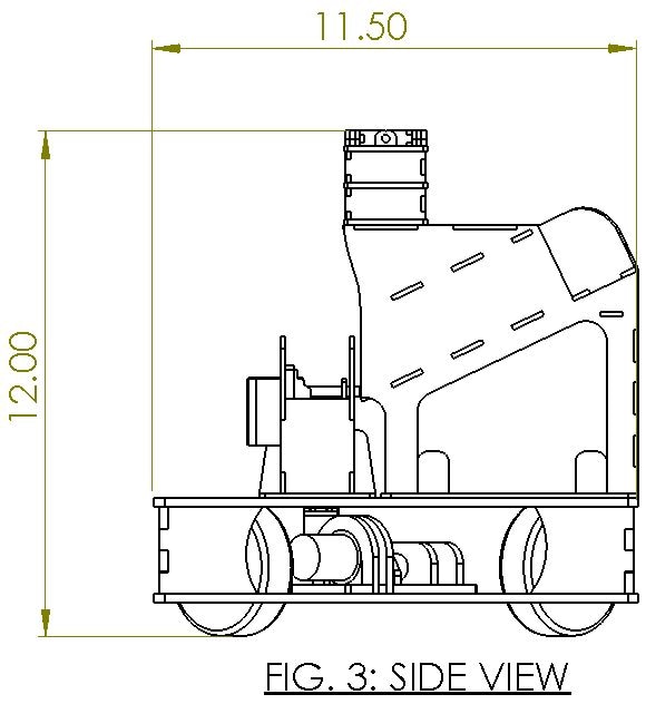
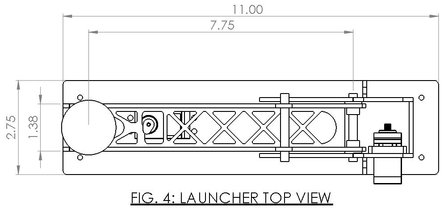
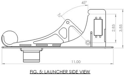
DRAWINGS
|
|
|
|
|
