Hall Effect Sensor
Click on the picture to view detailed calculations and explanations
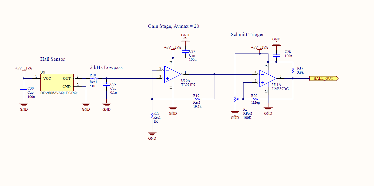
We used a DRV5053 Hall Effect Sensor to detect the frequency of the magnetic field produced by the coils at the staging locations in the game field. We basically pass the signal through a lowpass filter, a gain stage and a Schmitt trigger.
H-Bridge Circuit
Click on the picture to view detailed calculations and explanations
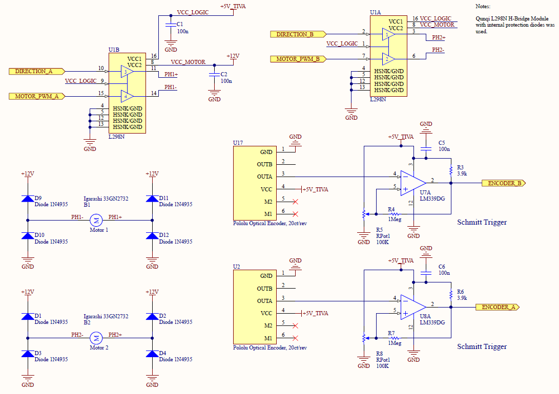
We drove our motors with an L298 H-Bridge from Amazon. Optical encoders from Pololu, and LM339 Schmitt triggers were used to measure the motor's speed.
LED Driver
Click on the picture to view detailed calculations and explanations
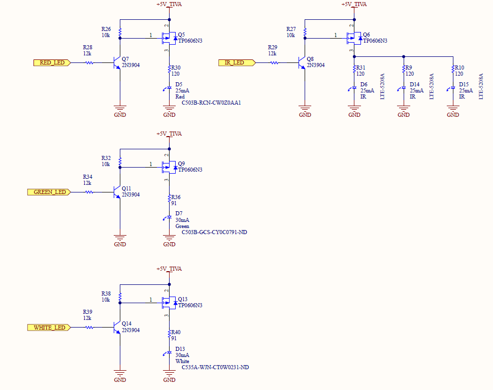
Initially we intended to use TLC5916IN for driving our LEDs using the SPI interface, however with the project deadline fast approaching we instead opted out for a simpler solution. These BJTs and MOSFETs controlled our LEDs just fine!
Ultrasonic Sensor Multiplexer Circuit
Click on the picture to view detailed explanations
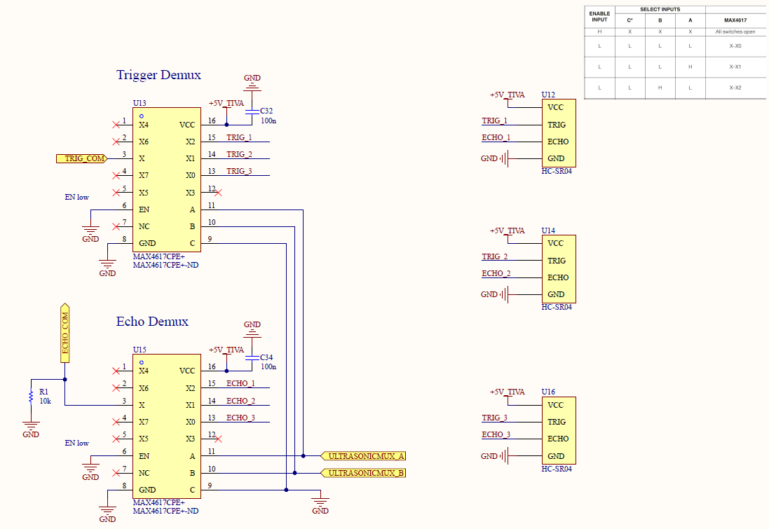
Two MAX4617 multiplexers were used to connect three ultrasonic sensors to the Tiva. We use software control to select and read the measurement from each of these sensors sequentially.
Power Distribution
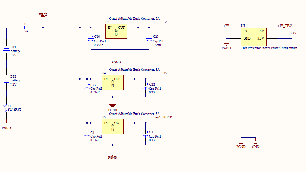
Click on the picture to view detailed explanations
Our robot was powered from two 7.2V NiMH batteries. A 5A fuse was used to protect our circuits. Three buck converters powered our robot - a 7V line was used to power the Tiva Protection Board, our drive motors were run from a 12V rail, and our servos were run from a 5V rail.
The 5V rail generated by the LDO on the Tiva Protection Board was used to power our analog circuitry. The LOC was powered by the 3.3V rail generated by another LDO on the Tiva Protection Board.
The 5V rail generated by the LDO on the Tiva Protection Board was used to power our analog circuitry. The LOC was powered by the 3.3V rail generated by another LDO on the Tiva Protection Board.
Servo Circuit
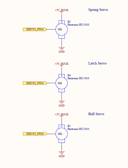
Click on the picture to view detailed explanations
Three servos controls our shooting mechanism. The ball servo dispenses the ball into the shooting ramp. The latch servo latches the shooter in place so the spring servo can tension the spring. The latch servo can then unlatch and let the shooter shoot the ball away.
Top Schematic - Tiva and the LOC
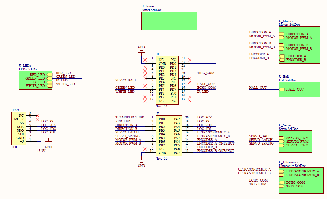
A Tiva TM4C123G Launchpad was the brains behind our robot. It was mounted on a Tiva Protection Board supplied by the SPDL. Above is the schematic diagram for our entire system. The LOC (an XBee module used to communicate with the game board computer) is shown in the bottom left corner.
Schematics for our entire electrical system can be found below:
| 218b_schematicsfinal_03122017.pdf |
